This instruction for mounting a sensor on a salient pole generator where it is possible to route the sensor cables through a stator ventilation duct. Other types of machines will need some modifications to the workflow.
One
Find a hatch on the back of the stator where you can access the back of the stator core.
It is not always this easy to access the back of the stator core.
Two
Find a pole gap in a suitable position relative to the opening in the stator back.
There can be a lot of things in the way in the pole gap.
Three
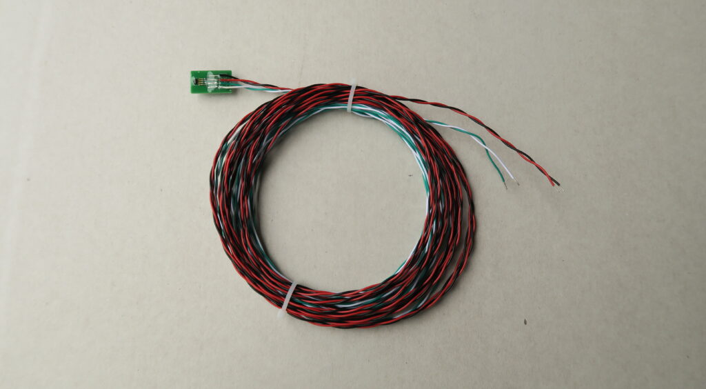
Get out your sensor.
The cables are glued to the small circuit board and everything is covered in insulating clear coat.
Four
Unroll the cables to make sure there are no kinks and knots.
Make sure the cables are not tangled before you start threading them through the stator.
Five
It is easier to get the sensor cables through the ventilation duct if you tape them together.
Unless the ventilation ducts are very narrow you should be able to fit taped cables like these through them.
Six
Start threading the cables through a ventilation duct. Magnetic end effects will affect the flux measurement if the sensor is glued to the very end of the stator. A position on the third or fourth stator packets eliminates this problem.
In this image you can see the sensor cables being threaded out of the stator between the third and fourth core packets.
Seven
If possible, get someone to gently pull at the cables as they come out the back of the stator.
The Hall sensor cables coming out through a ventilation duct.
Eight
When the cables are through it is time to check the position of the sensor and how it will fit on the stator tooth without covering the next air duct.
For this measurement the sensor was turned downwards and glued to the fourth core packet.
Nine
It is now time to put clue on the sensor and hold in place. As you move the sensor in place, make sure the cables are pushed into the ventilation duct and that they don’t make a loop before they enter the ventilation duct.
Here all the work had to be done one hand so it got a bit messy.
Ten
Before starting the generator, it is recommended to check the sensor and cables by measuring the resistance between the four sensor cables. The resistances should be around 1 kohm regardless of combination of cables. Values between 800 and 1200 ohms are good.